Instructions to generate symbols, footprints, and 3D Models for Altium Designer 21 and Altium Designer are provided below.
The following instructions explain how to import the downloaded Ultra Librarian files into Altium Designer 21 to generate symbols, footprints, and 3D Models.
Import a Schematic Symbol and PCB Footprint:
1.Open Altium Designer.
2.Choose File > Run Script from the menu.
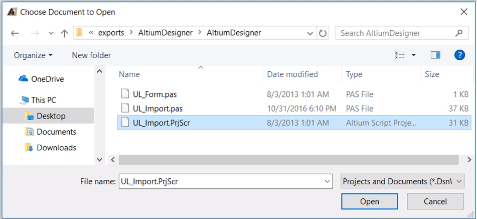
3.Select Browse > From File… and select the downloaded UL_Import.PrjScr.
Note: This script is included in the download from Ultra Librarian and is located in the AltiumDesigner folder.
4.Select Open and OK.
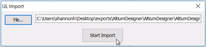
5.In the UL Import Dialog box, select File.
6.Select the .txt file and Open.
Note: This file is included in the download from Ultra Librarian and is located in the AltiumDesigner Folder. The naming convention of this file will differ depending on the download method.
7.Select Start Import.
Note: A dialog box may appear regarding the text font of the symbol. Click OK.
The PCB footprint and schematic symbol have been generated and can be viewed with selection in the project window.
Mapping the 3D Model to PCB Footprint:
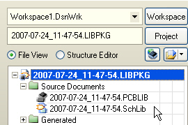
1.In the Projects tab, double click the PCBLIB Source Document.
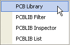
2.Select the Panel button located in the lower right corner. Choose PCB Library.
3.In the PCB Library Panel, select the desired footprint.
Note: Any variations of the PCB footprint are included in the Ultra Librarian download and footprint generation.
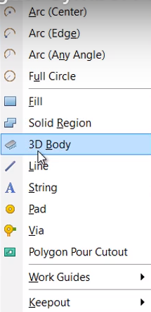
4.Select Place > 3D Body from the menu.
5.In the Choose Model dialog box, select the .step file. Select Open.
Note: If selected, this is included in the download from Ultra Librarian and is located in the folder beginning with the download date.
6.Select the center of the PCB Footprint.
7.To view the 3D Model, select View > 3D Layout Mode.
View the Imported Component:
1.In the Projects tab, double-click the SCHLIB Source Document.
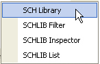
2.Select the Panel button located in the lower right corner. Choose SCH Library.
3.In the Schematic Library Panel, double click the imported component to view the schematic symbol, PCB footprint, and 3D Model.
The instructions that follow explain how to import files you download from Ultra Librarian into Altium Designer.
Before you begin your import, extract the files included in your zip download folder and save the files in a directory you can easily access from Altium Designer. The downloaded files are:
•UL_Form.dfm
•UL_Form.pas
•UL_Import.pas
•UL_Import.prjScr
To import a footprint, symbol, and 3D Model into Altium Designer:
1.Open Altium Designer.
2.Choose the File > Open menu items and select the downloaded UL_Import.PrjScr. This script is located in the AltiumDesigner folder you downloaded.
3.Click the Open button to automatically run the script.
4.Select UL_Form.pas > Open.
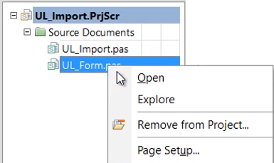
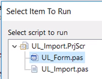
5.Select Run. ![]()
6.Select UL_Form.pas again.
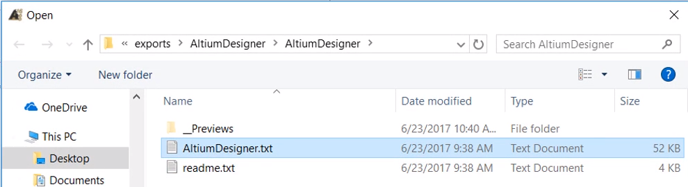
7.Choose the AltiumDesigner.txt file included in your Ultra Librarian download.
8.Click the Start Import button.
After the import is complete, you can view and save the generated footprint and symbol.
To include the PCB 3D Model:
1.Open the PCB footprint.
2.Select the Place > 3D Body menu items.
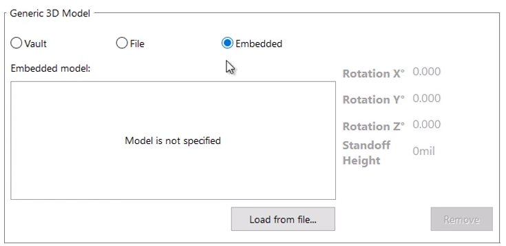
3.Select the Generic 3D Model radio option. ![]()
4.Under the 3D Model section, select the Embedded radio button and click the Load from file button. ![]()
5.Select the step file downloaded from Ultra Librarian.
6. Add a snap point and axes.
7.Click OK and place the body. The 3D Model is available from the 3D view.
To view your imported components:
1.Select the menu items: View > Workspace Panels > Systems > Projects.
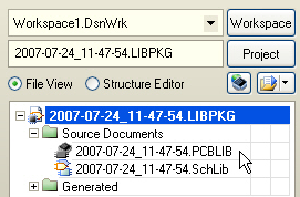
2.Double-click the PCBLIB item you want to open from the Source Documents list.
3.Click the PCB button located in the lower right corner of the screen and select PCB Library from the pop-up menu.
You can browse through the components to view.
To view imported schematic symbols:
1.Click the tab labeled Projects and double-click the SchLib item you want to open.
2.Click the SCH button located in the lower right corner of the window.
3.Choose the SCH Library menu item from the pop-up menu to display items in the schematic library side panel.
4.Browse through the components and view the schematic symbols in the display window.